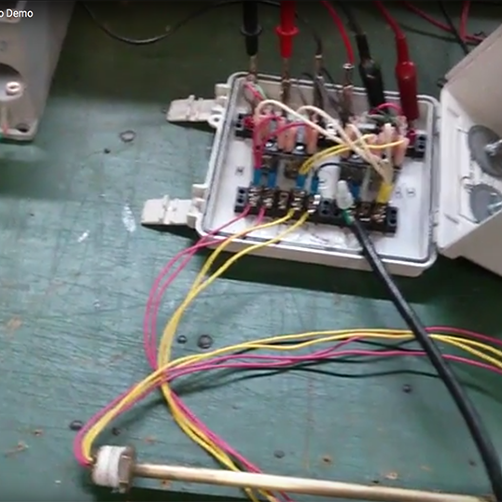
The video above runs a working bench setup: a float switch in the tank, a level control relay handling the load, and an alarm reporting the condition the control circuit is not supposed to reach. This page covers what the demo moves past quickly, mainly why the three pieces are wired the way they are and what you need to nail down before ordering.
The Float Switch Is Not the Load Contact
The most common mistake in a field-built level control is a float switch wired straight to a pump motor or a solenoid valve.
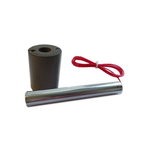
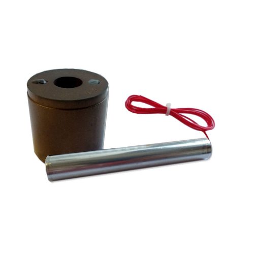
Most float type level switches carry a low contact rating, on the order of tens of VA. They are built for control voltage and control current. A pump motor pulls locked rotor current on every start, and a solenoid coil throws an inductive kick back down the line on every release. Either condition erodes a reed contact fast, and a switch that tested clean on the bench begins sticking closed a few thousand cycles into service.
The relay carries that duty instead. The float switch drives the relay input at low current, and the relay output carries the motor or valve. On the Dual Level Pump Control Relay used in the demo, the board applies 12vac across the float switch contacts and switches 10A at the output. The float contact never sees the load.
Fill Logic and Drain Logic
That relay takes two float switches, one at the low set point and one at the high set point. The pair defines a band instead of a single trip point, which is what keeps a pump from short cycling around one level.
In drain mode the relay sits de-energized with the tank empty. Rising liquid closes the low float and nothing changes at the output. When the level reaches the high float, the output transfers and the pump runs. It holds through the drop past the high float and reverts only when the low float opens.
Fill mode inverts the sequence. The relay starts energized, the output transfers to de-energized when the high float closes, and it stays there until the low float opens on the way back down.
Mode is a wiring choice on the same board, not a different part number. Part number sets supply voltage and output rating: R-DLC120-NEMA4 at 120vac and 10A, R-DLC230-NEMA4 at 230vac and 5A, R-DLC24-NEMA4 at 24vac and 10A. All three arrive in a NEMA 4/4X wall mount enclosure with a 6ft cord and conformal coated circuitry, UL/cUL recognized. Board-only versions cover panel integration where you already have an enclosure.
Give the Alarm Its Own Float Switch
The alarm in the demo is a TLA series audible and visual alarm: NEMA 4/4X thermoplastic housing, 360-degree red indicator, 85db buzzer at 10 feet, watertight cord grips, and a test and silence toggle on the face.
The wiring detail worth copying from the demo is that the alarm runs off a dedicated float switch set above the high control point, not off the control circuit. Two reasons for that.
An alarm sharing the relay’s logic reports what the relay believes is happening rather than what the liquid is doing. If the output stage fails or a contactor welds, the control circuit and the alarm go quiet at the same moment, which is the one scenario the alarm exists to catch.
An alarm set inside the normal control band also chatters on every cycle, and operators stop reacting to it within a week. Place the alarm float above the high control float, at the level that indicates the pump has failed to keep up, and it only sounds on a real fault.
Supply Voltages Across the Three Devices
The three devices do not have to run on the same supply, so treat them as separate decisions.
Relay supply follows your control power, available at 120vac, 230vac, or 24vac.
Alarm supply is independent of the relay. TLA-500 runs on 120vac, TLA-512 on 12vdc, TLA-524 on 24vdc.
For tanks without convenient power, TLA-512-BAT carries a 12VDC lithium ion rechargeable battery, which also keeps the alarm live through a supply interruption that would take the rest of the loop down with it.
Commissioning the Loop
Verify the sequence by hand before the tank goes into service. Lift each float in order and confirm four things: the low float closes with no change at the output, the high float closes and the output transfers, the high float opens with the output held, and the low float opens and the output reverts.
Check the alarm separately. The test and silence toggle proves the buzzer and lamp work without filling the tank, but it proves nothing about the alarm float or the wiring between them. Lift that float by hand at least once at commissioning, then fold it into the same inspection interval as the rest of the loop.
Remote Notification
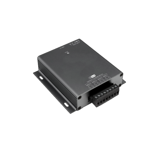
An 85db buzzer only helps when someone stands within earshot of it. On unattended tanks and remote sites, the Dry Contact Email Sender accepts a dry contact closure from the alarm float and sends an email on the event, which covers off-shift conditions and unmanned locations.
Specifying the Set
Innovative Components builds the float switches, level control relays, and tank level alarms shown in the demo, so one conversation covers the whole loop instead of three vendors. Relays and alarms typically ship in 1 to 3 business days, and custom controllers run 5 to 7.
Have five things ready when you call: tank depth, your two control set points, the alarm point above them, your control voltage, and the load you are switching. Talk to an engineer and we will size the switches, the relay, and the alarm against those numbers. If you would rather start from the switch side, browse standard single level float switches or custom multi-level float switches.